Tuesday, 22 November 2011

Creating Beams


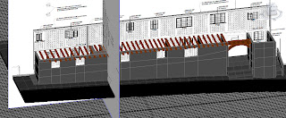
The Guildhall has many beams running throughout the building. In order to create these I simply used the box shape. To get the right shape and size I used the scale tool, and then it was just a case of following the outline shown in the reference planes. Once in the right place, I held shift and dragged another beam out, moving that one into the correct position. I continued this cloning process until all of the beams were in place.

However, the problem with the Guildhall is that it slopes - the back of the building is not the same height as the front. In order to solve this problem I had to convert all of the beams to editable polys and use the rear reference plane to adjust the height of the beams there, so that they were in the right position on both sides of the building.

Once finished, I added the main central beam, using a similar process. In order to create the wooden arch at the front I used a cylinder shape, converting to an editable poly and deleting one side in order to leave a half-cylinder. I had to use the bridging process in order to create new faces where the bottom half had been removed. Then it was a case of dragging the vertices until it form the correct arch-shape I was looking for.

Tuesday, 15 November 2011

Ground Floor - Basic Layout


In order to create the basic layout of the ground floor, I started by creating rectangular 2D shapes that followed the floorplan. By clicking on the smaller edge, holding shift and dragging it, I could ensure that the rectangles followed the floorplan, creating a new face whenever there was a window, door or new wall. I then extruded these rectangular faces up to the necessary height of the ground floor walls. However, this method caused problems later on when it came to removing polygons for the windows and doors. So, I started the process again.

Having already created the extruded rectangles, I could see how many faces were required on each wall, so this time I created 3D cuboids from the standard primitives menu. In the parameters section I could change how many segments the shape had. By looking at the extruded rectangles and counting how many faces were required, I could set the number of width segments. I then set the number of height segments to four. The bottom segment for the brick layer at the bottom of the Guildhall, the next two layers could be used for window and door placement, and the top layer would be the space between the top of the window and door frames and the next level.

Once I had created all of the cuboids and positioned them correctly using the reference planes, I had to convert them all into editable polys in order to move the shape edges into the correct positions for windows and doors. This was easily achieved using the reference planes. Once the edges were positioned I could remove the polygons where the windows and doors would be situated.

Upon removing these polygons, I was left with open faces around the border of the window or door. In order to resolve this, I used the bridge tool. By clicking on the inner and outer edges I could create a new polygon that bridged the gap, thus leaving me with a solid shape with holes cut out for the windows and doors. By doing this to all of the walls, it leaves me with the basic layout of the ground floor level.

Wednesday, 2 November 2011

Reference Planes


In order to start the group project, I took the architect's plans of the Guildhall and imported them into Adobe Photoshop CS4. Once there, I pasted all four elevation images into one document and aligned them so that the image could be used to make reference planes. I achieved this using the ruler tool, in a similar way to when I created the reference planes for my head model. This technique was easier for the Guildhall as, being a structure rather than an organic object, the features are quite linear. I also imported the architect's images of the floor plans into Photoshop in order to create reference planes for the building layout.

Once I had completed the Photoshop work, I created a plane in 3D Studio Max. I then went into the materials section and added a bitmap setting to the material diffuse property. The bitmap image was of the aligned Guildhall plans from Photoshop. Once setting the self-illuminate option to 100 and ensuring that the viewport settings were correct for showing the bitmap in full quality, I applied the material to the plane. I then applied the UVW-mapping modifier to the plane.

The UVW-mapping modifier allowed me to move the gizmo (the image) around without moving the planes. Once I had the left elevation shown on the plane and had reduced the plane to the right size, I then cloned the plane and repeated the process for all four elevations. I then created a new reference plane for the ground floor layout. Here I have five reference planes set up from which to create the model of the Guildhall.